info@senger.com.au +61 413 886 800
Recent work · WA

Recent Work

Three recent jobs, told the way they happened: what we were asked, what the check found, and the smallest change that fixed it. The images are from the actual analysis. Clients, sites and drawings stay private.

01 · Cantilever rack · Pilbara, wind region D

1,000 kg per level is not 250 kg per arm.

An existing steel cantilever rack: four frames, five levels, 1,000 kg per level. The working assumption was the load divided by four arms, 250 kg each. It was wrong three times over.

  1. Load share. A long length on four equally spaced arms behaves like a continuous beam. The two inner arms carry 1.1/3 of the level each, 367 kg, not 250.
  2. Torsion. An angle’s shear centre sits at its heel, so stock on the horizontal leg twists the arm. It passed in bending alone and failed once torsion was included: utilisation 1.21 at 250 kg with the bundle at the toe.
  3. Cyclonic wind. In regions C and D, wind on the stored material can add more force than wind on the rack itself. That decides the anchors, the footings and the cyclone procedure.
+47% on the inner arms 1.21 utilisation as built 0 racks replaced

None of it meant a new rack. The arms were boxed with a second angle and welded for the real moment and twist, the base stiffened, the anchors placed where the lever is longest, the footing pads thickened, and a cyclone procedure written.

How the rack check works
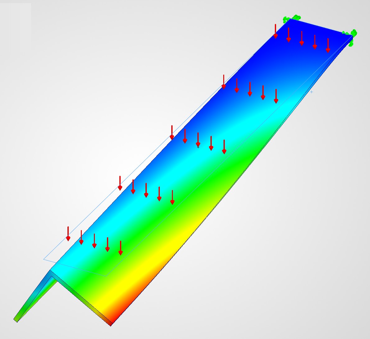
Finite element model of a steel angle arm under load, coloured by displacement, showing the toe of the bearing leg dropping as the open section twists
Displacement on a loaded angle arm. The toe drops as the open section twists, which a bending-only check never sees.
02 · Mobile steel frame · design verification

Is it good for the load? As drawn, it was not.

A client sent drawings of a mobile steel frame and one question. Before changing anything, we checked the design exactly as drawn: hand calculations to AS 4100 first, then finite element analysis on the parts the hand calculations flagged.

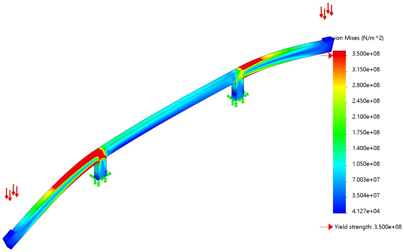
The first image settled it. One small RHS member, loaded the way the frame is actually used, past yield along a long band of its top and bottom faces. Not a hot spot at a sharp corner that can be argued away. That member had to change.

  1. The client’s concept was kept. Same frame, same way of working. The job was the smallest set of changes that makes it pass, not a redesign.
  2. Every change justified in writing: the check that fails without it and the result with it.
  3. The whole frame checked as a second-order model over 32 ultimate load cases, member by member.
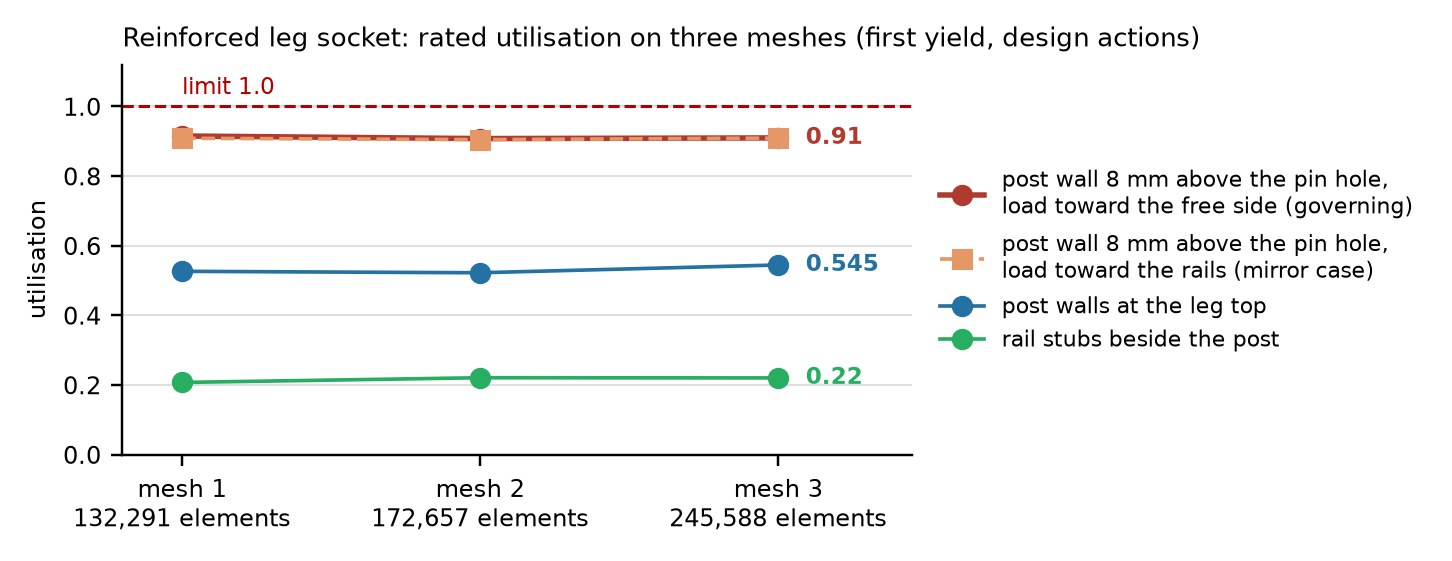
  4. The critical connection modelled as a solid with pin contact on three meshes. Utilisation held at 0.91 on all three.
  5. Stability checked in every phase of operation, not only when parked, with the operating procedure written to match the design.
32 ultimate load cases 3 meshes, 132k to 246k elements 0.91 on every mesh

A colourful plot proves nothing until it agrees with a hand calculation and survives a mesh refinement.

Structural design and checks
Finite element model of a steel RHS member coloured by von Mises stress, with red bands along the top and bottom faces showing stress past the 350 MPa yield strength
The member as drawn. Everything red is past yield (350 MPa), along the faces, not at a corner.
Chart of utilisation at the reinforced connection on three finite element meshes, holding at 0.91 against a limit of 1.0
The reinforced connection on three meshes. If a number moves when the mesh is refined, it is not a result yet.
03 · Commercial kitchen exhaust · Perth fit-out

About $15k cheaper. Nothing was cut.

The first layout was the usual one: canopy, 20 m of grease duct across the ceiling, fan wherever the roof looked clear, a 3 m stack. It complied. It also carried assumptions the Standards do not support.

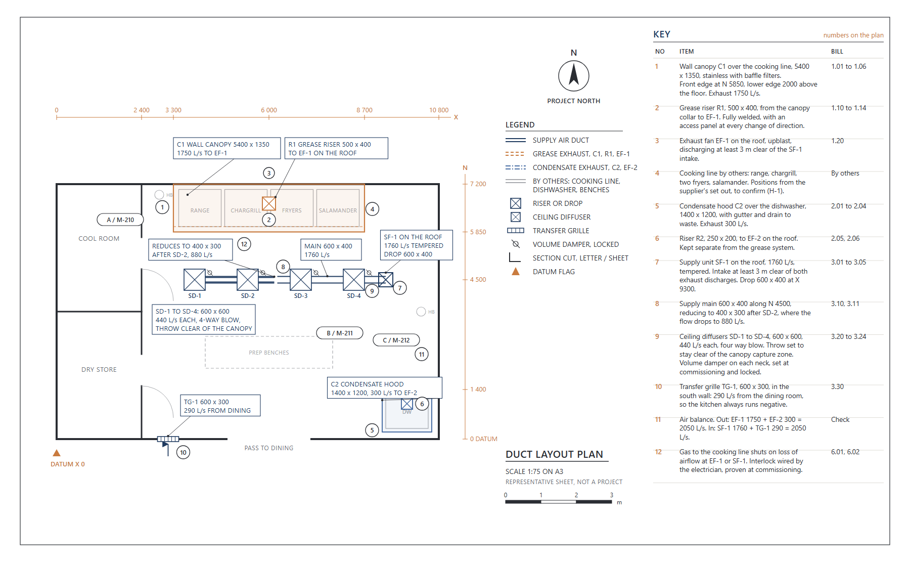
  1. Fan directly above the hood. 20 m of horizontal grease duct became a 2.5 m riser. No bends, 2 access doors instead of 10, a 1.1 kW fan instead of 1.5 kW.
  2. Hood sized to the cooking line, not to the canopy the last tenant left. AS 1668.2 sets airflow on the hood perimeter, and the old canopy would have needed 13% more exhaust, and more make-up air, for good.
  3. The 3 m stack checked, not assumed. In AS 1668.2-2012 that height applies to Type A effluent. Kitchen exhaust is Type B, and this council’s guideline set no height.
  4. Gas ovens change the air. Under AS/NZS 5601.1 the trigger for flued appliances is 0.4 MJ/h per m³ of room. The 3 that people quote is the flueless limit.
20 m → 2.5 m of grease duct 10 → 2 access doors ≈ $15k less installed

None of this is exotic. It is reading the clause, doing the arithmetic, and deciding before the contractor prices.

The seven decisions, with the numbers
Representative kitchen exhaust layout sheet showing a hood, a short vertical grease duct riser and a roof fan
Representative layout sheet in the same style as the package. The project drawings stay with the client.

Have a job that needs a second look?

Send the drawings or a few photos. Free scoping call, then a fixed fee before any work starts.

Send the drawings
Or call +61 413 886 800 · Email info@senger.com.au